TenniBear: a robotic tennis ball collector
December 2024 to April 2025
I built TenniBear after noticing team tennis practices involved more ball pickup than actual drilling.Thank you to the Iron Panthers (FRC 5026) for letting me borrow old FTC parts (U-channels, mecanum/compliant wheels, DC motors, D-shafts).


This footage is from varsity team practice in April 2025. I finished TenniBear in late March, and brought it to practices regularly for the remainder of the season (~1.5 months).
1. TenniBear Concept Sketches
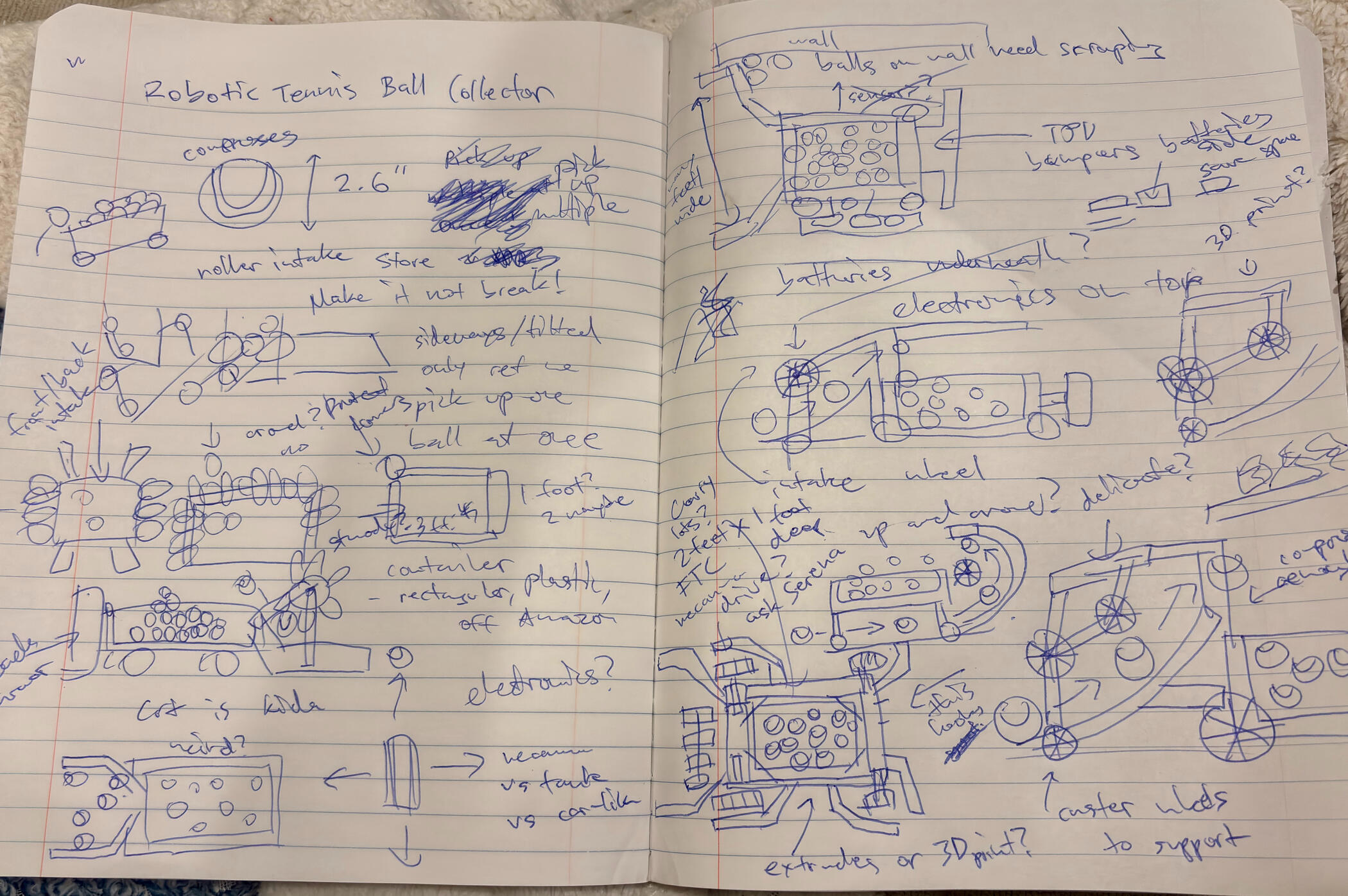
Coming up with an initial plan for TenniBear took 2 weeks of brainstorming over my junior year winter break. I thought about how to intake tennis balls, protect delicate electronics, move around the court, and source materials/parts. Here is a page from my notebook from December 2024.
2. TenniBear CAD
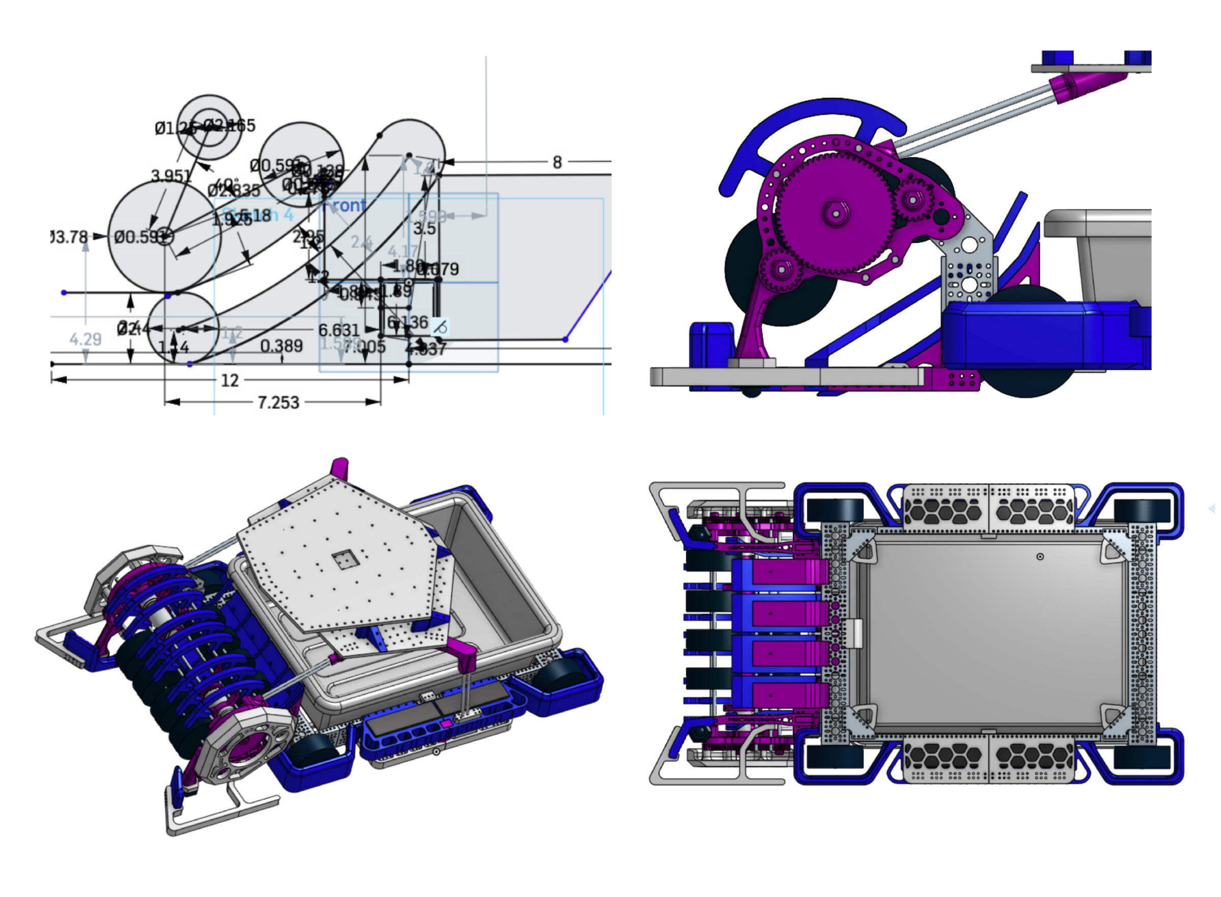
I decided to collect tennis balls by rolling them up a ramp into storage. I then started prototyping geometry in Onshape. I repurposed old FTC parts from my school team for the frame, motors, and compression wheels. I added TPU armor (blue) to absorb impacts. The caps on each side of the intake (also TPU, in white) were suggested by my physics teacher Mr. Bennett. I printed gears and structural elements out of PLA (purple). The top plates are for holding and protecting electronics, and I machined them out of acrylic. Four batteries are stored on the side of the chassis. My design is capable of picking up multiple balls at once and storing roughly 80 at a time.
~December 2024 to January 2025
3. TenniBear Ball Intake Testing
After a few iterations of intake geometry, this one performed consistently. It’s a bit shaky because I didn’t yet have aluminum D-shafts capable of stretching across the whole intake (hence the blue shaft couplers). I later greased the gears to reduce friction and noise. I frequently resorted to stuffing blankets under my door at night to prevent the sound of drilling and testing from waking my parents.
~January 2025
4. TenniBear Electronics: Main Power Distribution Board
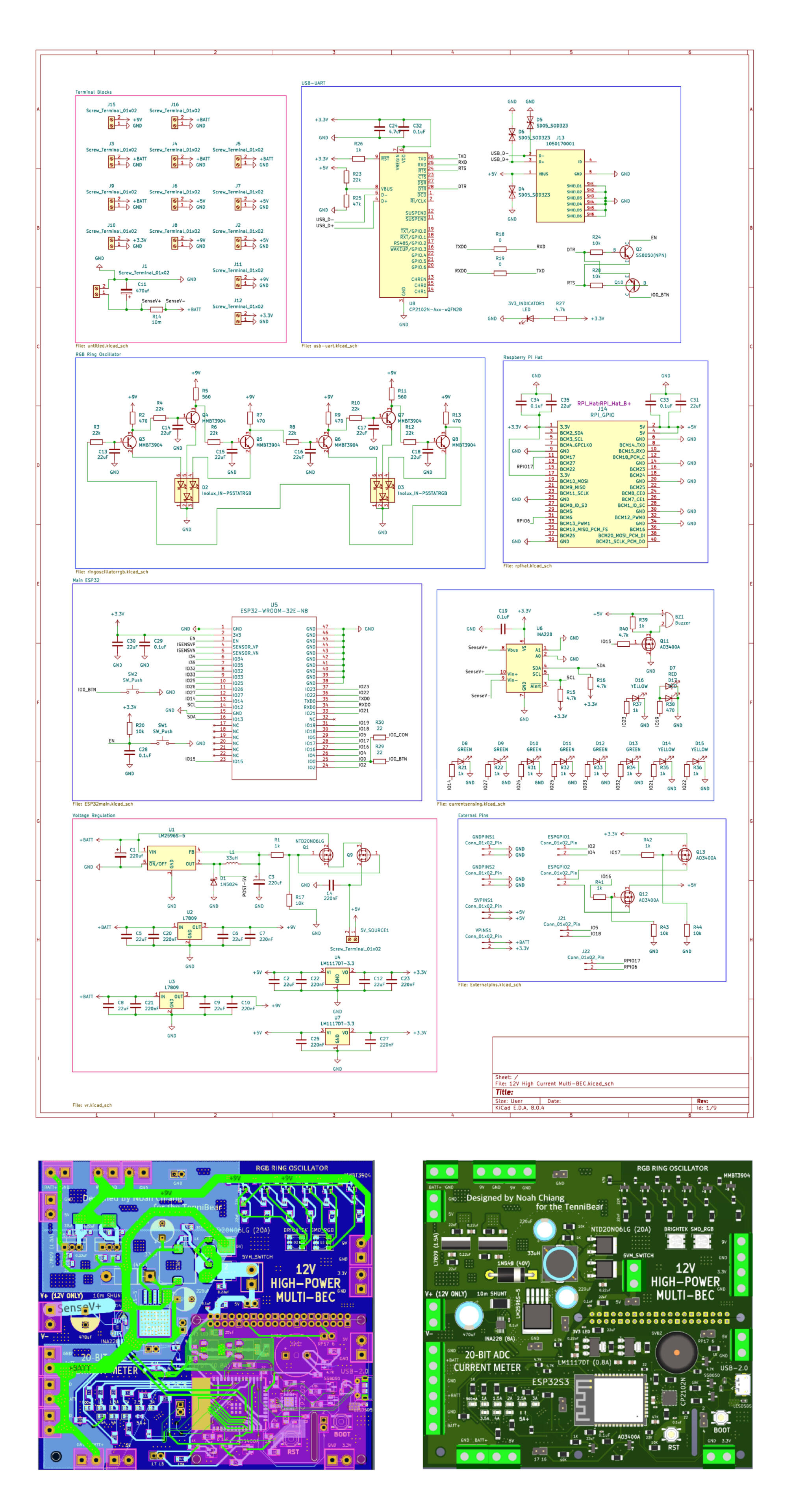
Instead of buying individual power distribution modules, I decided to design my own singular board to supply all peripheral electronics of TenniBear. I used a switching voltage regulator to produce 5V (from 12V), and linear regulators to get 9V and 3.3V. I added a current sensor IC connected to an ESP32 module to monitor power consumption in case of overcurrent. I also modified a ring oscillator to light two RGB LEDs (a circuit I saw online and was fascinated by). I made sure to place lots of terminal connections and large decoupling capacitors. The board was initially meant to be a Raspberry Pi hat, but I ended up just connecting the pins manually because of height constraints. Designed on 6 layers in KiCad, roughly 200x200mm.
~January 2025 to February 2025
5. TenniBear Electronics: H-Bridge Motor Driver, Voltmeter, RGB Fan Driver
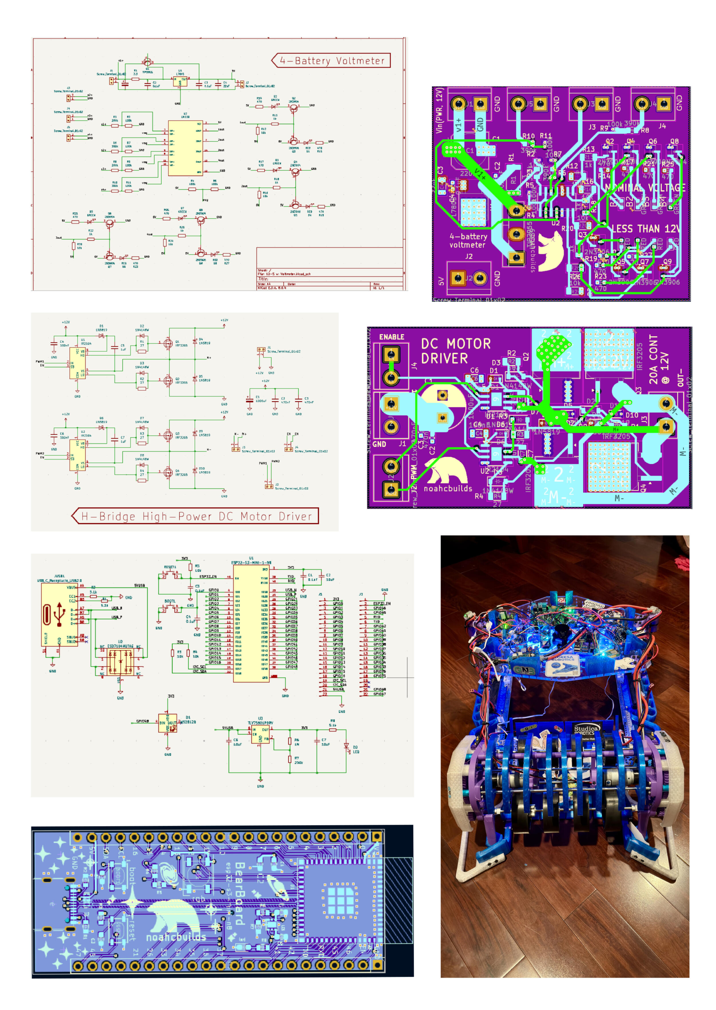
These are more boards I designed for TenniBear. I wanted to be able to monitor the status of the 4 LiPo batteries used, so I created a voltmeter (top board) using resistive dividers and a comparator to indicate if a battery drops below 12V (12.6V nominal). Below the voltmeter is a bidirectional DC motor driver for the intake motors (separate from the drive motors, which I used Pololu drivers for). Bottom left is a ESP32 microcontroller board I designed for my school’s Electronics Club, and repurposed to drive the RGB lights of the two cooling fans. They all performed well, and were powered by the main distribution board.
~February 2025
6. TenniBear Wiring + Coding
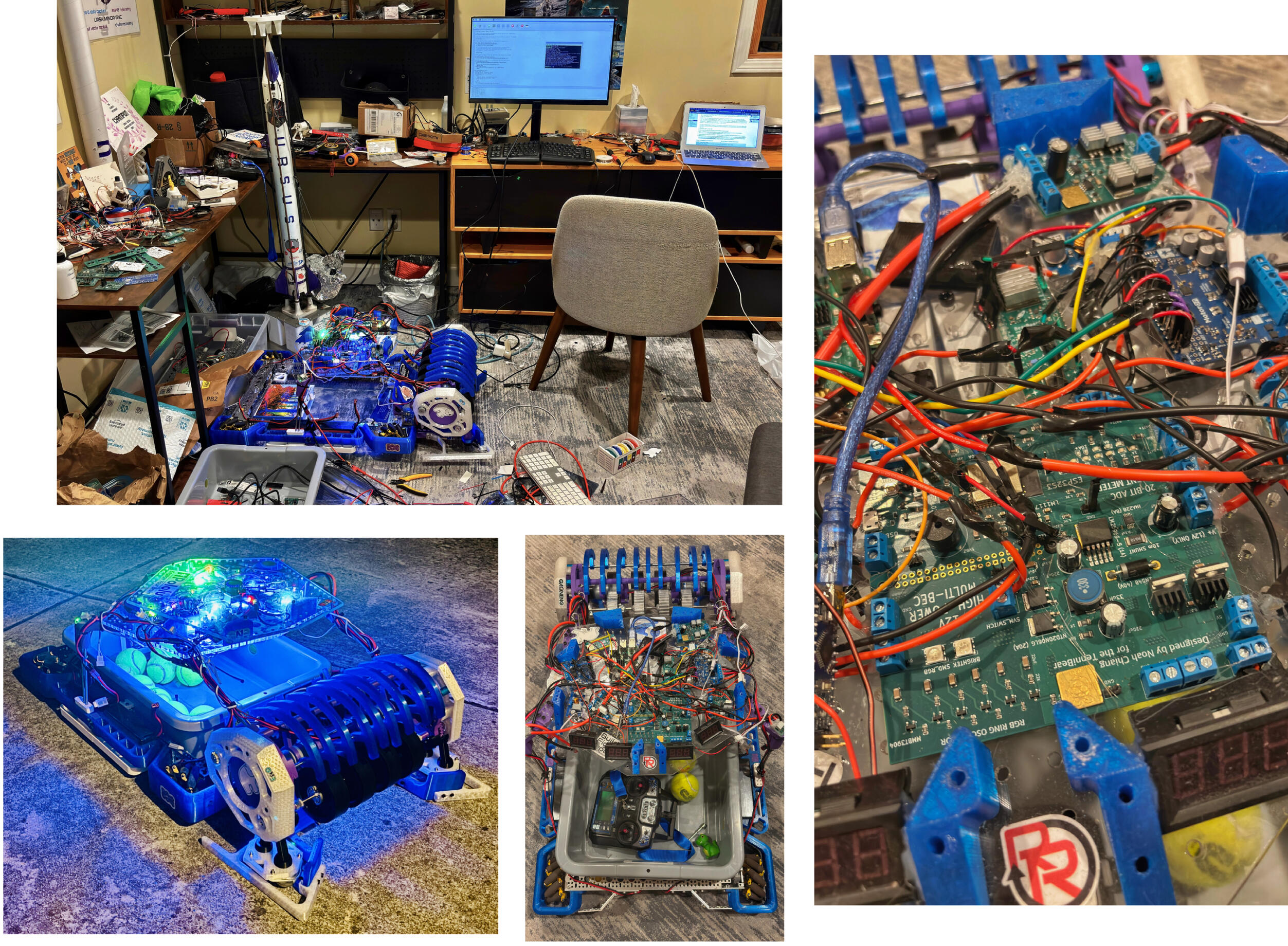
I made sure to create a communal ground between the batteries, and used high-gauge wire wherever possible. Connecting and soldering all of the electronics took a few weeks of datasheet-checking and planning. I short-circuited a few linear regulators in the process, but replaced them relatively easily.One challenge was the remote communication protocol: trying to get my drone radio transmitter (which I also use for Combat Robotics) to communicate with the Raspberry Pi was difficult, mainly because the Pi cannot read PWM signals. I improvised by using a Nano to read them, which then communicated with the Pi over serial. I wrote around 30 lines of Python for the Pi to unlock omnidirectional movement capabilities for the Mecanum drivebase (assisted by FTC guides and the Pololu driver Python library).
~February to March 2025
7. TenniBear Testing + Troubleshooting


Before bringing TenniBear to practice for the first time, I ran tests at my local courts with teammates. We discovered that the metal caster wheels I’d designed to support the intake easily wore down, and so I replaced them with rubber caster wheels. The second line of intake wheels didn’t get as much grip on the balls as I would’ve liked, so I printed ridged TPU tracks and wrapped them around the wheels. Both fixes worked like a charm. One improvement I would like to make before next season is adding metal hubs to the intake gear-motor connection, as the 3D printed hubs sometimes slip. A useful addition would be making TenniBear autonomous: I hope to learn computer vision and pathfinding in the future.
~March to May 2025